Ejector sleeves
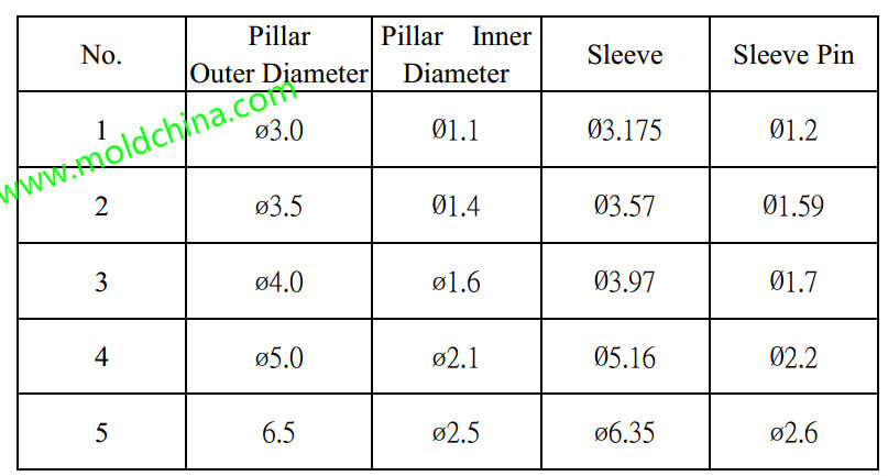
1) The application of ejectors sleeves is required when a product features a hollow pillar structure and a great height. The matching relationship between pillars and sleeves is shown in the diagram below:
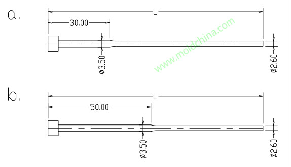
When a product features a pillar that is equipped with shockproof rubber, the ø3/16” + ø1.7 sleeve should be selected. If number 5 sleeve option is selected, there will come the stepped sleeve pin, of which the dimensions are shown in the diagram. For mold base below 30 x 40, category A sleeve pins should be applied; for mold base over 30 x 40, category B sleeve pins should be applied. See the diagram:
The order should be placed in the following format:
ø1/4” x sleeve length x ø3.5 x 30 x ø2.6 x L
ø1/4”x sleeve length x ø3.5 x 50 x ø2.6 x L
If a CD slider needs a sleeve, the sleeve dimensions will be unified as:
ø 6.35 x sleeve length x ø1/8” x sleeve pin length, in consideration of convenient pin replacement.
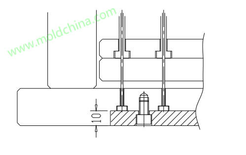
2) Sleeve pins are often fixed in plastic injection mold by headless screws. However, when several sleeve pins are very close to each other, briquettes and hex socket head cap screws will be used to fix them.
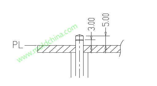
3) Usually, the fixing holes of a button employ the sleeve ejector, with the standard ø3.57 x ø1.59 sleeve selected without exception. When it is not possible to use the standard size sleeve, it has to be guaranteed that the hole size is kept unchanged while the outer circle is appropriately enlarged, to make it possible for the application of a standard sleeve. The matching relationship between the sleeve pin and the cavity is shown in the diagram below:
4) Prevent sleeve from contacting with the knock-out hole.


