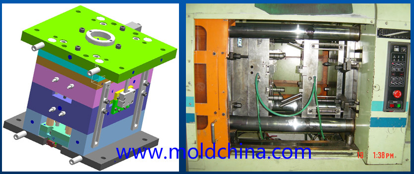
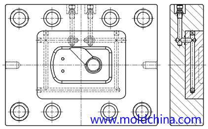
Definition of injection mold cooling system:
Injection mold cooling system: AKA. injection mold temperature control system
Heat or cool the mold to keep its temperature within a reasonable range.
-Mold cooling medium: water, oil, beryllium copper (BeCu) and air, etc.;
-Mold heating methods: hot water, steam, hot oil and heating rod, etc.
Influence of Mold Temperature on Different Plastics
- For plastic materials with great fluidity (PE, PP, HIPS, and ABS, etc.), lowering the mold temperature helps reduce stress cracking (the mold temperature is usually around 60°C);
- For plastic materials with poor fluidity (PC, PPO and PSF, etc.), raising the mold temperature helps reduce the internal stress of the plastic product (the mold temperature usually ranges between 80°C and 120°C).
Influence of mold temperature on quality of molded plastic products
- Temperature too high: The plastic products deform greatly after mold release, and it is easy to cause flashing and sticking;
- Temperature too low: Leading to poor melt fluidity, as well as such surface defects as silver streaks, flow lines, and underfilling;
- Uneven temperature: The plastic products shrink unevenly, resulting in warping deformation.
Mold temperature directly affects the injection cycle
- Injection mold cooling time takes up about 80% of the injection cycle.
Ways to improve mold temperature control
- Appropriate size of cooling lines: diameter 5-13mm (3/16″-1/2″).
- Select mold materials with high thermal conductivity.
- Reasonable plastic product design.
- Proper cooling circuit.
- Enhance the cooling of the thick areas of a plastic product.
- Fast and slow cooling.
- Strictly control the temperature difference between the coolant outlet and inlet.
Key considerations for injection mold cooling channel design
1.Which is more important, cooling or ejection?
2.Try to keep the thermal balance of the mold, so that the temperature is uniform in each part of the mold.
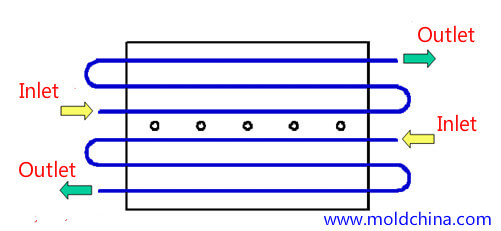
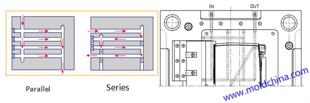
3.A parallel cooling channel is not preferred
Location of cooling lines:
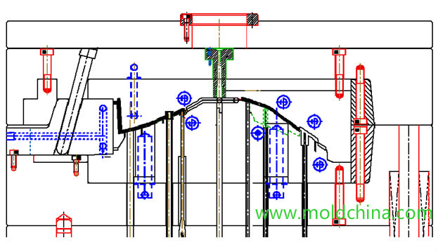
1.Try to keep a consistent distance between the coolant and the filled plastic in the cavity, 10-15mm is preferred. The center distance of the coolant is about 5D.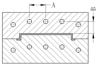
2.The cooling lines should not be close to locations where the melt flows finally meet;
3.Prevent the cooling lines from interfering with other mechanisms in the mold, and maintain a steel part of 3mm in the middle;
4.The coolant for cavity insert should be as close as possible to the filled plastic, and that of the core insert should be set as far as possible to the outer edge. When the mold cavity / core is too big, the coolant must be in contact with it.
5.For the BeCu mold, coolant may go straightly between plate A and plate B.
Coolant channel length design
The longer the coolant channel, the more difficult it is to process and the worse the cooling effect. The number of cooling line elbows should not exceed five.
The distance between the hoses should not be less than 30mm
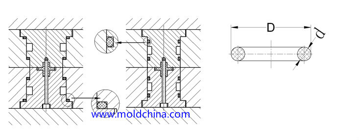
O-ring design
1.When the cooling channel passes through two inserts, a O-ring is added in the middle;
2.Try to avoid wear and shear on O-rings during assembly.
Empirical identification of injection mold cooling line diameter:
Mold width < 200mm: diameter 5-6mm (or φ3/16″-1/4″);
Mold width between 200 to 400mm: diameter 6-8mm (or 1/4″ – 5/16″);
Mold width between 400 to 500mm: diameter 8-10mm (or 5/16″-3/8″)
Mold width > 500mm: diameter 10-13mm (or 3/8″-1/2″)
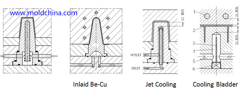
Mold core cooling
1.Core diameter ≤ 10MM: natural cooling;
2.Core diameter between 10 to 15mm: cooling with inlaid BeCu;
3.Core diameter between 15 to 25mm: jet cooling system;
4.Core diameter 25-40MM: cooling bladder + spacer
5.When mold core diameter is greater than 40mm and the height is less than 40mm, it is inconvenient to guide the coolant through to the center, so cooling from the lower surface is recommended.
6.When mold core diameter is greater than 25mm, cooling from the outer side can be adopted when it is inconvenient to guide the coolant through to the center.
